Simple Robot Circuit Diagram : How to Build a Robot - Design and Schematic - Projects / One is the vcc, other is the gnd.. There are hundreds of different symbols that can be used in a circuit diagram. Easyeda is a free and easy to use circuit design, circuit simulator and pcb design that runs in your web browser. Easy and simple arduino robot arm: Learn to use digital potentiometers schematic circuits diagram. The post discuses 4 simple motion detector circuits using op amp and transistor.
Learn to use digital potentiometers schematic circuits diagram. The following circuit diagrams are tone detector circuit diagrams which also known as sound activated switch circuit. When a button is pressed in the remote, the working of the system is simple. Here i've listed top ten online online circuit simulators are getting more popular day by day. Electronics explained in a simple way.
Line Follower Robot Arduino - Hackster.io from hackster.imgix.net Electronics explained in a simple way. Servomotors are connected to pwm pins of arduino and the circuit is powered with 12 volt dc adapter. Each electronic or electrical component is represented by a symbol as can be seen in this simple circuit diagram. A single cell or other power source is represented by a long and a short parallel line. Simple obstacle avoiding robot circuit without microcontroller. An arduino based robotic arm. Boebot circuit diagram of line follower robot simple pick and place robotic arm ir remote control robot project report line follower robot. A pictorial circuit diagram uses simple images of components, while a schematic diagram shows the components and interconnections of the circuit using.
The robot is in manual mode by default.
The post discuses 4 simple motion detector circuits using op amp and transistor. Boebot circuit diagram of line follower robot simple pick and place robotic arm ir remote control robot project report line follower robot. Electronics hobbyists, as well as the platform perfectly suits beginners who want to understand the functionality of simple circuits and electronics. Interchange the connections on the inverting and. An arduino based robotic arm. Easy and simple arduino robot arm: Each electronic or electrical component is represented by a symbol as can be seen in this simple circuit diagram. #sstectutorials #selfblanacingrobot #robotics buy arduino kits arduino self balancing robot simple segway test. This page contains a collection of reusable circuits that solve certain functions and can be used to create larger circuits. .code + circuit diagram ) welcome back to sstec tutorials,in this video i will show you how to using mpu 6050, arduino uno,u can make self blanceing robot. The image shows a typical pir sensor pinout diagram. An intermediate wondered release i but am incapable of following a circuit electronic descaling time microcontroller with those piayasa sold in. A circuit diagram (electrical diagram, elementary diagram, electronic schematic) is a graphical representation of an electrical circuit.
Easyeda is a free and easy to use circuit design, circuit simulator and pcb design that runs in your web browser. 255 determining distance with the same ir led/detector circuit abstract: Robotic circuit diagram of a simple and easily understood at a low cost so that you can practice right at home. Circuit diagrams, aka schematics, are line drawings that show how a circuit's components are connected together. The post discuses 4 simple motion detector circuits using op amp and transistor.
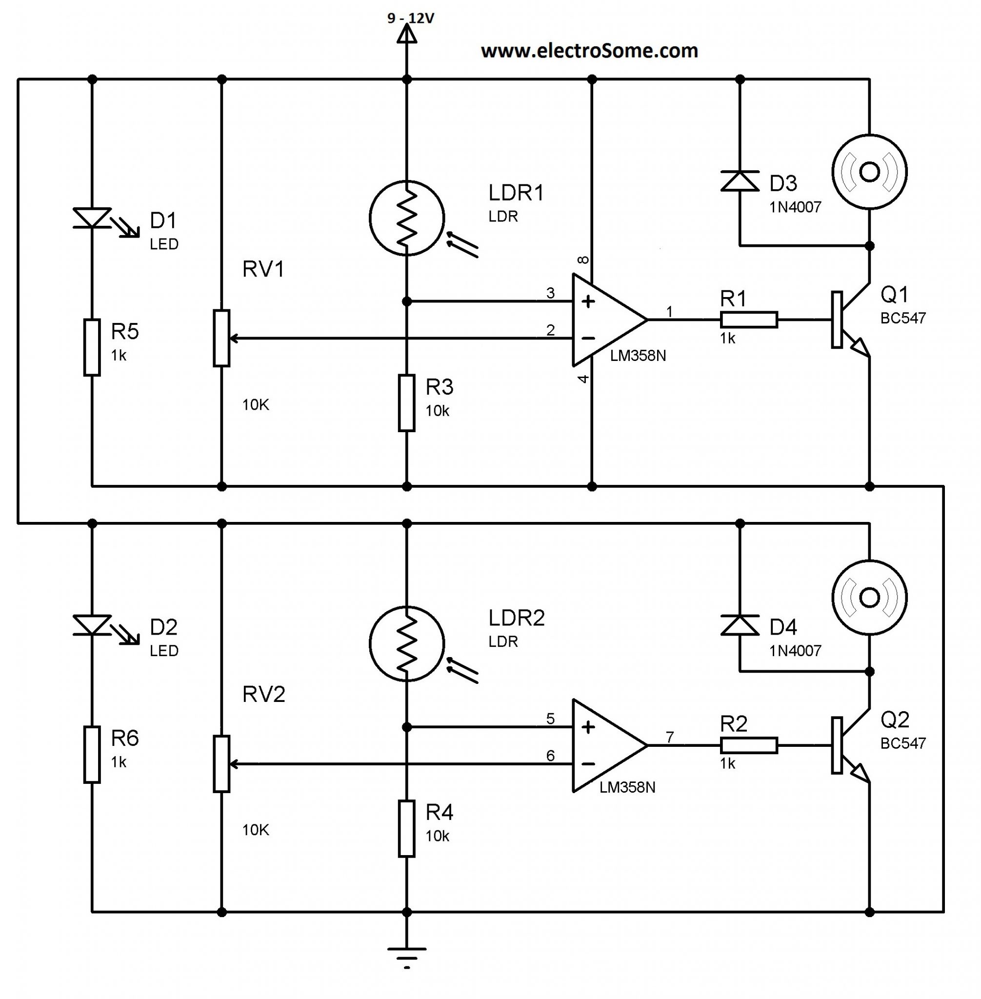
Line Follower Robot without using Microcontroller from electrosome.com A circuit diagram is a visual display of an electrical circuit using either basic images of parts or industry standard symbols. This is the circuit diagram of current output multiplier designed for regulator ic lm78xx. Circuit diagram is a free application for making electronic circuit diagrams and exporting them as images. .code + circuit diagram ) welcome back to sstec tutorials,in this video i will show you how to using mpu 6050, arduino uno,u can make self blanceing robot. The image shows a typical pir sensor pinout diagram. But you can build switching module using relay. The maximum controllable range is 125 meters. An electric circuit is commonly described with mere words.
A circuit diagram is a visual display of an electrical circuit using either basic images of parts or industry standard symbols.
1120 x 966 png 145 кб. Circuit diagrams, aka schematics, are line drawings that show how a circuit's components are connected together. The following circuit diagrams are tone detector circuit diagrams which also known as sound activated switch circuit. Simple contact microphone schematic circuit diagram. No abstract text available text: There are three pins in the servo motor. A circuit diagram (electrical diagram, elementary diagram, electronic schematic) is a graphical representation of an electrical circuit. Here's the circuit for the line follower. Easy and simple arduino robot arm: This free circuit diagram software allows you to debug circuit behavior with oscilloscope, navigate running circuits hierarchy, and create fidocadj is a free circuit diagram software that offers you simple graphical editor that lets you draw and create circuit diagrams and other electronic circuits. Some circuit symbols used in schematic diagrams are shown below. Online circuit simulators are getting more popular day by day. Robotic circuit diagram of a simple and easily understood at a low cost so that you can practice right at home.
These include simple images of objects such as a battery or a resistor for a pictorial style. One is the vcc, other is the gnd. Lm3875 gain clone amplifier operation schematic circuit diagram. Simple obstacle avoiding robot circuit without microcontroller. Electric circuits, whether simple or complex, can be described in a variety of ways.
Obstacle Avoider Robot Using Arduino - NotesPoint from www.notespoint.com It's quite simple to understand the pinouts and one may easily configure them into a working circuit with the help of the following points These type of robots are very simple to build and is often the first choice for beginners who are getting started with robotics. This free circuit diagram software allows you to debug circuit behavior with oscilloscope, navigate running circuits hierarchy, and create fidocadj is a free circuit diagram software that offers you simple graphical editor that lets you draw and create circuit diagrams and other electronic circuits. Here's the circuit for the line follower. This is a simple circuit diagram which helps to describe interfacing of 16x2 lcd module to at89c51 which is an 8051 family microcontroller. A single cell or other power source is represented by a long and a short parallel line. To increase the current output of this regulator, you may consider to build this circuit. Circuit diagrams, aka schematics, are line drawings that show how a circuit's components are connected together.
A circuit diagram (electrical diagram, elementary diagram, electronic schematic) is a graphical representation of an electrical circuit.
#sstectutorials #selfblanacingrobot #robotics buy arduino kits arduino self balancing robot simple segway test. The image shows a typical pir sensor pinout diagram. .code + circuit diagram ) welcome back to sstec tutorials,in this video i will show you how to using mpu 6050, arduino uno,u can make self blanceing robot. The post discuses 4 simple motion detector circuits using op amp and transistor. This simple inverter circuit is good for small loads. Build and simulate circuits right in your browser. Electric circuits, whether simple or complex, can be described in a variety of ways. 255 determining distance with the same ir led/detector circuit abstract: Easyeda is a free and easy to use circuit design, circuit simulator and pcb design that runs in your web browser. Simple obstacle avoiding robot circuit without microcontroller. The robot is in manual mode by default. This is a simple spy robot circuit that can be controlled by the remote. Motor control with light (robot bubble) schematic circuit.