Home › Unlabelled ›
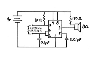
Tone Generator Circuit Diagram : Tone Generator Circuit Simple Calling Bell Circuit - The tone generator circuit described here is based upon 555 as a free running multivibrator.
Tone Generator Circuit Diagram : Tone Generator Circuit Simple Calling Bell Circuit - The tone generator circuit described here is based upon 555 as a free running multivibrator.. Last updated on june 15, 2019 by swagatam 4 comments. This is a 555 tone generator circuit based on ne555 timer ic. It can be used to produce dial tones in telephones or produce sirens in ambulances or vip vehicles etc or to generate melody tunes in toys, door bells etc. A simple tone generator that allows software control of auditory stimuli is described. A tone generator circuit can be used for various applications such as alarms, bells, indicators, etc.
The capacitors are used to reduce the noise. A simple tone generator that allows software control of auditory stimuli is described. At the heart of the circuit is an lm556 dual timer ic 1 shows the circuit of the triple mode tone generator, while fig. The heart of the circuit multi tone generator is um5561 ic (ic1) and the entire circuit is built around it. Shown below is internal structure of a multivibrator ic and its circuitry.
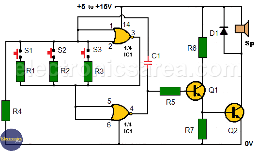
Build Your Own Tone Generator Musicworks Magazine from www.musicworks.ca What is a signal generator? Cricket chirping generator circuit diagram october 3, 2010. It can send electrically generated. The circuit is a simple monotonous alarm generator system with three inputs. 2 tone ringtone generator circuit. Ne555 is a very famous ic used in many circuits and performs variety of tasks. The circuit for tone generator is shown in below diagram. Frequency table (a4 = 440 hz).
The circuit can be operated with 6 volt dc.
Again be careful as you follow the circuit diagram to wire everything correctly as this is extremely important to the working of the entire system. Lm1036n tone controlled amplifier circuit with tda7375 schematic circuit diagram. Last updated on june 15, 2019 by swagatam 4 comments. Ne555 is a very famous ic used in many circuits and performs variety of tasks. Such periodic signals produce a variety of beeping sounds when coupled with an audio transducer. Knowing your tinnitus frequency can enable you to. This is a 555 tone generator circuit based on ne555 timer ic. Cricket chirping generator circuit diagram october 3, 2010. The following 2 tone ringtone generator circuit shows how to configure the ic ls1240 as a two tone musical signal generator circuit. The simple top10 electronic circuits for beginners includes dc lighting circuit, rain alarm, simple temperature monitor, touch sensor,led circuit, etc. The circuit for tone generator is shown in below diagram. Discover 5 circuit diagram (main pcb assy/beam control block) / (main pcb assy/keyscan block). Here is a simple triple mode tone generator circuit that generates three different tones.
The signal generator is also known as the generator which produces the tone, arbitrary and the digital pattern waveforms. Tone generator circuit using 555 timer bird sound generator, ambulance siren generator these are some circuit diagrams of the sound generators. For frequency modulation, the modulator circuit is placed after the vco. The tone generator circuit described here is based upon 555 as a free running multivibrator. There are different types of signal generators with different level of capability.
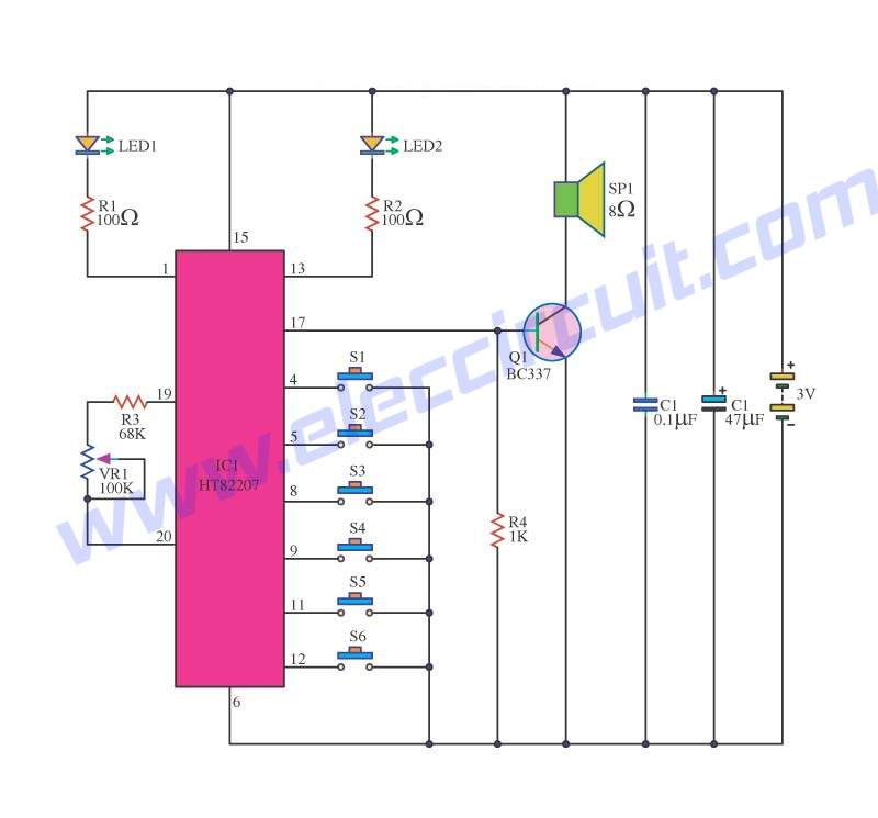
Learn Melody Tone Generator Circuits Using Ht82207 Um3491 Mm5837 Eleccircuit Com from www.eleccircuit.com To filter out the noise from supply voltage capacitors are placed across terminals as shown in the diagram. At the heart of the circuit is an lm556 dual timer ic 1 shows the circuit of the triple mode tone generator, while fig. Last updated on june 15, 2019 by swagatam 4 comments. Generally, tone generator circuits include triangle, square, sawtooth & sine wave generator circuits. The circuit provides for the simultaneous generation, timing, and amplification of three different tones. Frequency table (a4 = 440 hz). The tone generator circuit described here is based upon 555 as a free running multivibrator. Again be careful as you follow the circuit diagram to wire everything correctly as this is extremely important to the working of the entire system.
Here is a simple triple mode tone generator circuit that generates three different tones.
Tone produced by the circuit. Transistor t2 is driver transistor and used to drive loud speaker. A tone generator circuit usually uses the 555 timer ic to produce a range of sounds. Shown below is internal structure of a multivibrator ic and its circuitry. This is a 555 tone generator circuit based on ne555 timer ic. To filter out the noise from supply voltage capacitors are placed across terminals as shown in the diagram. Speaker / buzzer (without internal generator). Last updated on june 15, 2019 by swagatam 4 comments. What is a signal generator? The simple top10 electronic circuits for beginners includes dc lighting circuit, rain alarm, simple temperature monitor, touch sensor,led circuit, etc. The circuit can be operated with 6 volt dc. A tone generator consists of a square, triangle, sawtooth periodic wave generator circuits, commonly square wave generators. Frequency table (a4 = 440 hz).
The heart of the circuit multi tone generator is um5561 ic (ic1) and the entire circuit is built around it. Such periodic signals produce a variety of beeping sounds when coupled with an audio transducer. The circuit for tone generator is shown in below diagram. Simple tone generator circuit diagram. At the heart of the circuit is an lm556 dual timer ic 1 shows the circuit of the triple mode tone generator, while fig.
Multitone Generator Circuit Open Door Indicator Using Cd4001 Electronics Area from electronicsarea.com Simple delta wave generator schematic circuit diagram. Tone produced by the circuit. For frequency modulation, the modulator circuit is placed after the vco. There are different types of signal generators with different level of capability. The circuit can be operated with 6 volt dc. The circuit provides for the simultaneous generation, timing, and amplification of three different tones. Ne555 is a very famous ic used in many circuits and performs variety of tasks. 2 tone ringtone generator circuit.
Frequency table (a4 = 440 hz).
Circuit diagram of two tone music generator using ic ls1240. Discover 5 circuit diagram (main pcb assy/beam control block) / (main pcb assy/keyscan block). Frequency table (a4 = 440 hz). Last updated on june 15, 2019 by swagatam 4 comments. At the heart of the circuit is an lm556 dual timer ic 1 shows the circuit of the triple mode tone generator, while fig. The block diagram of the signal generator is shown in the figure below. Ne555 is a very famous ic used in many circuits and performs variety of tasks. For frequency modulation, the modulator circuit is placed after the vco. Static void tone(uint8_t octave, uint8_t note) {. This electromechanical tone generator was designed as a project for the electrical and computer engineering department at utah state university. April 26, 2012 by ashutosh bhatt. It can be used to produce dial tones in telephones or produce sirens in ambulances or vip vehicles etc or to generate melody tunes in toys, door bells etc. Transistor t2 is driver transistor and used to drive loud speaker.